Project 01 Aug 2025 – May 2026 MSc Thesis · SPS, NISER Advisor: Dr. Ashok K. Mohapatra

Generation of Microtrap Arrays for Single Atom Trapping

MSc thesis work on shaping light into stable microtrap arrays with spatial light modulators, and on building the rubidium cold-atom apparatus.

Stage 01 · Context

A thesis on single-atom trapping

Single atoms can be held in tightly focused optical traps. This MSc thesis, carried out at the School of Physical Sciences, NISER, works on generating arrays of such microtraps and on preparing the experiment that will load them. This project was carried out under a larger project of establishing a neutral-atom quantum computer undertaken by our group.
Stage 02 · Foundations

Beam propagation and optics

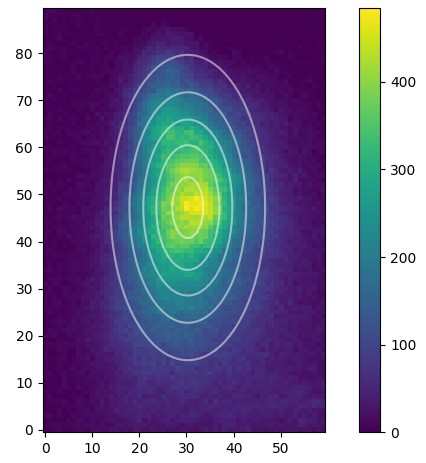
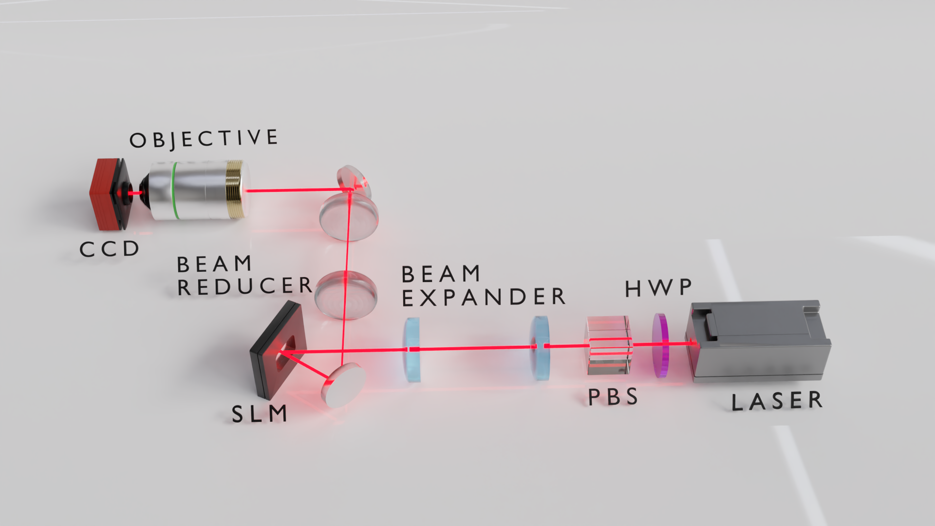
The groundwork covered quantum optics and the propagation of beams, both Gaussian and non-Gaussian, together with ray optics. I worked on setting up and testing the SLM [Holoeye Pluto 2 - NIR 011], using the inbuilt software to error correct. The input beams were also characterized and a plan for active fedback loop along with the dynamic trap array was decided.

Setup render
A render of the setup.

Stage 03 · Trap Generation

Microtraps from a spatial light modulator

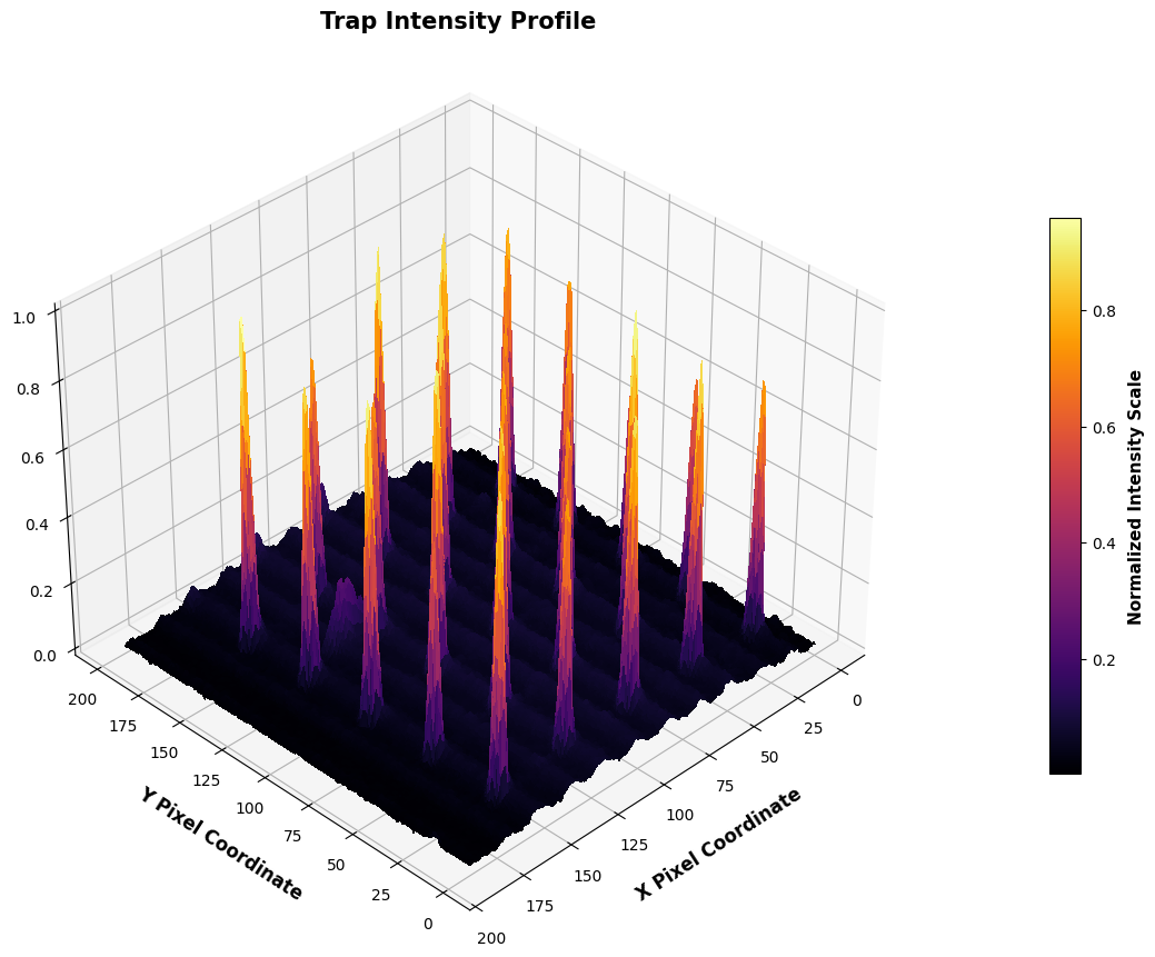
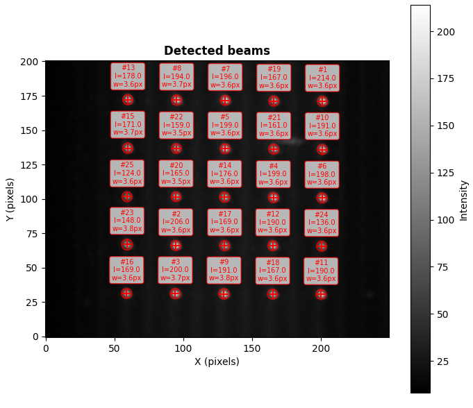
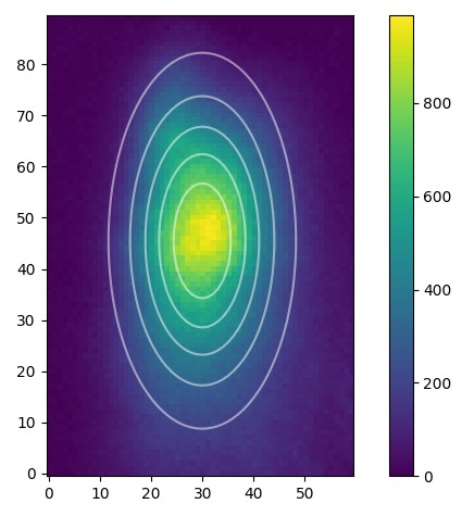
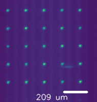
The microtraps were simulated using modified Gerchberg–Saxton algorithms [Weighted and Compressive Sensing] and then achieved experimentally using SLMs. The traps were fitted and characterized using a Gaussian fit, and the theoretical output was scaled to the experimental observation heuristically.

5x5 trap
The generated pattern.
3D intensity plot
3D intensity plot for the generated pattern.
Trap fitting
Fitting the pattern using a Gaussian fit.

Stage 03 · Multiple Traps

Confirming the capabilities of the code

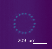
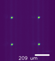
  • To confirm the capabilities of the code, multipple such arrays were generated, each using minimal weighting and compression.
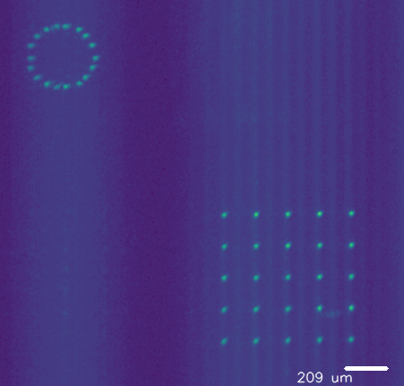
  • Trap outputs displayed here ran for 30 iterations, with 1/16th sampling. Most traps showed >90% intensity uniformity. Traps with large spacing, however, showed loss of intensity near the edges of the frame.
Circle Trap
Circular trap generation.
2x2 trap
2x2 trap array.
mixed
Large trap with circular and 5x5 trap array.

Stage 04 · Apparatus

Preparing the Rb MOT and optical dipole trap

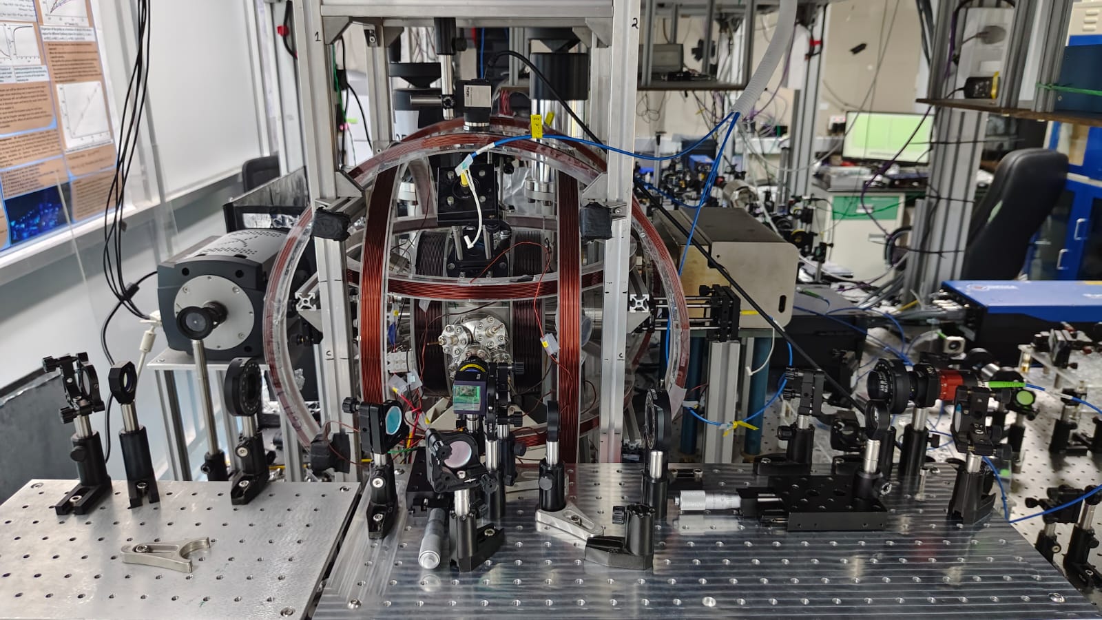
  • We use a 3D MOT setup for our trapping. Since the setup had not been used in years, we had to prepare and characterize the MOT coils and the required electronics, including an in-house AOD controller.
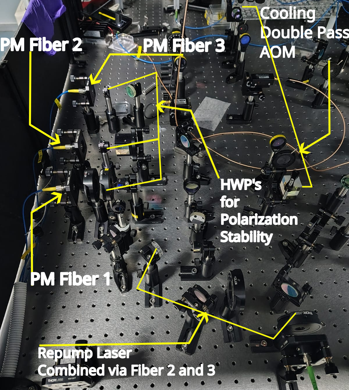
  • We then set up the cooling and repump beams and set up a shared setup for the MOT imaging line and single-atom trapping beam. The MOT beams were characterized and stabilized using differential polarimetry and long-term power study.
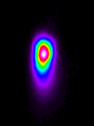
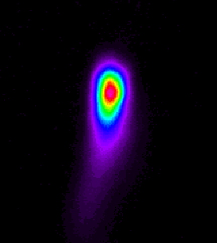
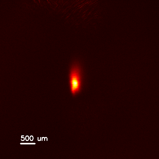
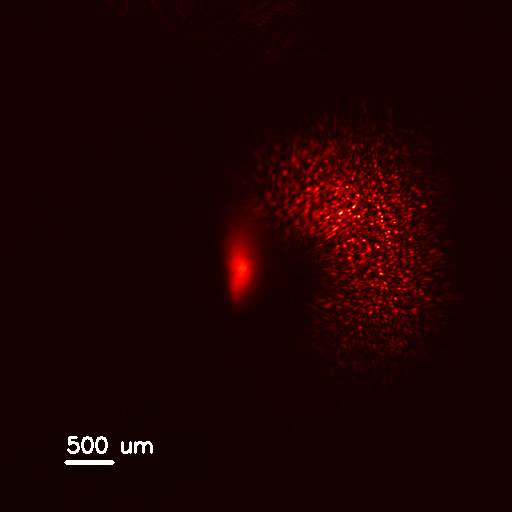
  • The MOT was characterized using fluorescence count and later re-aligned for higher atom count and stability.
  • This work was done in collaboration with a good friend, Hrishikesh Malladi.
MOT setup
The MOT setup.
MOT_Andor_Held
The MOT cloud with mag field on.
MOT_Andor_Released
The MOT cloud with mag field off.

Stage 05 · ODT

Setting up the Single-Atom Trap

  • Before setting up the trap, we calculated the shift from the relevant sources of error [gravity, geomagnetic field, chronmatic shifts, etc.].
  • We then set up a 2f imaging line for the imaging of the MOT cloud, sharing the setup with the ODT [through a BS & PBS].
  • We then align the trapping beam using the repump [to localize the cloud in a small region] and the on-resonance [F=2 to F'=3] beam [to determine the alignment of the cloud to the beam focus].
ODT setup render
The ODT & Imaging setup.
ODT setup
A render of the setup.
Cloud without alignment
MOT cloud before alignment.
Cloud with alignment
MOT cloud after alignment.
Atom count before alignment
Count before alignment.
Atom count after alignment
Count after alignment.

Stage 06 · Next Steps

Future directions

While a lot of the work wasn't show here, we planned three major extensions beyond the thesis period:

  • Creating sub-diffraction limited traps with spatially squeezed structured light [A very interesting paper has already been published on it by another group].
  • Implementing a feedback loop that uses a camera to automate corrections (Zernike) using test patterns [something we tried to implement but never could do].
  • Moving from a magnetometry setup with limited visibility to a glass cell with easier access [Something I struggled with because of the many size constraints from the windows, length from lens, etc.].
  • Using a high-NA objective to get to smaller beam waists and ideally, to the single atom level [The objective has been successfully designed and implemented by the group!].